
Search This Supplers Products:Power AdapterLED Power SupplyPower AdapterBattery ChargerMedical Power SupplySwitching Power Supply
Accurately measure power ripple
time2019/05/15
- Accurately measuring power ripple is an art in itself. In the example shown in Figure 1, a junior engineer completely misused an oscilloscope. His first mistake was to use an oscilloscope probe with a long ground lead; his second error
Accurately measuring power ripple is an art in itself. In the example shown in Figure 1, a junior engineer completely misused an oscilloscope. His first mistake was to use an oscilloscope probe with a long ground lead; his second mistake was to place the loop and ground lead formed by the probe near the power transformer and switching components; his last One mistake is to allow excess inductance between the oscilloscope probe and the output capacitor. This problem appears as a high frequency pick in the ripple waveform. In the power supply, there are a large number of high-speed, large-signal voltage and current waveforms that can be easily coupled to the probe, including the magnetic field coupled from the power transformer, the electric field coupled to the switching node, and the common mode generated by the transformer's inter-winding capacitor. Current.
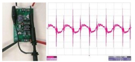
Figure 1 Poor measurement results from incorrect ripple measurements
The measured ripple results can be greatly improved with the correct measurement method. First, bandwidth limitations are often used to specify ripple to prevent picking up high frequency noise that is not really present. We should set the correct bandwidth limit for the oscilloscope used for the measurement. Second, by removing the probe "cap" and constructing a pickup (as shown in Figure 2), we can eliminate the antenna formed by the long ground lead. Wrap a small length of wire around the probe ground connection point and connect the ground to the power source. This can reduce the length of the tip exposed to high electromagnetic radiation near the power supply, further reducing pickup.
Finally, in an isolated power supply, a large amount of common mode current flows through the probe ground connection point. This creates a voltage drop between the power ground connection point and the oscilloscope ground connection point, which appears as ripple. To prevent this from happening, we need to pay special attention to the common mode filtering of the power supply design. In addition, winding the oscilloscope leads around the ferrite core also helps to minimize this current. This creates a common-mode inductor that reduces the measurement error caused by the common-mode current while not affecting the differential voltage measurement.
Figure 2 shows the ripple voltage for this identical circuit using an improved measurement method. In this way, the high frequency peak is really eliminated.
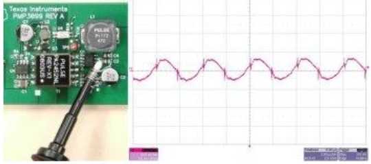
Figure 2 Four minor changes greatly improve the measurement results
In fact, after integration into the system, the power supply ripple performance will be even better. There is almost always some inductance between the power supply and other components of the system. This inductance may be present in the wiring, or only the etching is present on the PWB. In addition, there is always an extra bypass capacitor around the chip, which is the load on the power supply. Together, these form a low pass filter that further reduces power supply ripple and/or high frequency noise. In extreme cases, the filter has a cutoff frequency of 400 kHz when the current flows through a one-inch conductor of 15 nH inductor and 10 μF bypass capacitor for a short period of time. In this case, it means that the high frequency noise will be greatly reduced. In many cases, the filter's cutoff frequency will be below the power supply ripple frequency, potentially reducing ripple significantly.
Experienced engineers should be able to find ways to use this approach during their testing.