
Search This Supplers Products:Power AdapterLED Power SupplyPower AdapterBattery ChargerMedical Power SupplySwitching Power Supply
Efficient auxiliary power adapter
time2006/03/13
- The two positions of the voltage selection jumper are used to select whether to operate under 110V or 220V AC power adapter, and rectifier D~D2 can effectively supply 110V. In this case, the effective 110V AC power adapter can also supply 110V cooling fan
The figure shows a more efficient version of the previous circuit. This circuit uses the bridge rectifier D~D2 of discrete components to eliminate power dissipation on the feed resistors R1 and R2 in the converter. Such a circuit design is very useful for working under AC supply voltages of 110V/220V. The two positions of the voltage selection jumper are used to select whether to operate under 110V or 220V AC power adapter, and rectifier D~D2 can effectively supply 110V. In this case, the effective 110V AC power adapter can also supply 110V cooling fan, so the same fan can work under two input voltage values (in order to meet safety requirements, the insulation level of the fan should be suitable for higher Working under voltage).
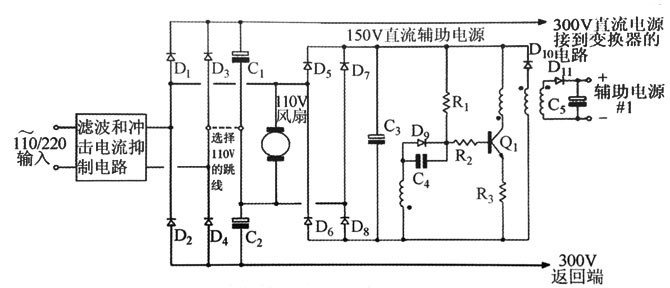
The self-oscillating flyback type auxiliary power adapter converter with 110V AC cooling fan can be used with F110V AC cooling fan, which can be used under two input voltages.
Note: When the working power adapter is a 220V AC adapter input, the jumper between C1 and C: should be removed. In this case, the load on the 300V DC power adapter must exceed the fan and auxiliary power adapter load to ensure a DC reset at the midpoint of C1 and C2. Therefore the circuit is only suitable for applications where the output maintains a minimum load. Although the ripple current load generated by the fan and auxiliary conversion circuits in most applications may only account for a small percentage of the total load, the appropriate capacitors C1 and C2 should be selected to withstand this ripple current load.
Main conversion transformer drive auxiliary power adapter
It is apparent that one winding of the main conversion transformer can provide the required auxiliary power adapter when the main converter is operating. Some means are needed during the start-up of the circuit to provide auxiliary power to the control circuit. Then in the following sections, several startup methods are introduced.
Low noise distributed auxiliary converter
High frequency sine wave power distributed system
The auxiliary power system discussed earlier uses a hard switching method (square wave). The disadvantage of this type of system is that the switching edges are steep and easily radiate high frequency noise and are coupled to the distribution conductors and transformers of the main control system.
The trend in modern high-power systems is to connect to other power adapters and computer control systems using embedded microcontrollers and industrial interface systems. Such systems typically use a multi-layer PCB and perhaps several different and isolated auxiliary power adapters. Obviously, any high frequency noise injected into the internal or external auxiliary power adapter or control line is not allowed.
While good placement and filtering can reduce unwanted noise in hard-switching systems to acceptable levels, a more efficient method is to use a high-frequency sine-wave system where the switching edges are not particularly steep and therefore do not Excessive high frequency noise.