
Search This Supplers Products:Power AdapterLED Power SupplyPower AdapterBattery ChargerMedical Power SupplySwitching Power Supply
Multi-output flyback switching power adapter
time2006/03/09
- The flyback unit combines the functions of an isolation transformer, an output inductor, and a freewheeling diode in a transformer. This combination of electromagnetic integration makes the circuit very cost effective and efficient and stable DC output.
The flyback unit combines the functions of an isolation transformer, an output inductor, and a freewheeling diode in a transformer. This combination of electromagnetic integration makes the circuit very cost effective and efficient and stable DC output.
This technique is especially useful for multi-output applications where multiple semi-stable outputs are to be obtained from a single power adapter. The main disadvantage is that large ripple current flows through the transformer and the output components, reducing efficiency. Due to this limitation, the power of the flyback converter is usually limited to less than 150W.
The designer should pay attention to adding load line shaping components (buffer circuits) for Q to make Q1 work in the safe working area.
Expected characteristic
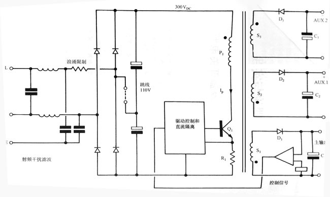
As can be seen from the example shown in the figure, the main output is closed-loop controlled and therefore fully adjustable. The auxiliary output is only half-adjusted, and the power adapter and load regulation accuracy is about 6%. If a good adjustment is required, an additional secondary regulator is required.
In a flyback power adapter, although the switching converter is highly efficient, the secondary regulator is typically linearly energy consuming. For small current outputs, the standard 3-terminal IC regulator is especially useful. Due to the pre-conditioning provided by the main output closed-loop control pre-regulator, the energy consumption in the linear regulator is minimized. In some applications, the closed-loop control regulator can control two or more outputs simultaneously.
Since most low-cost flyback converters do not have additional secondary regulators, over-specified requirements are not desirable. The main attraction of such converters is simplicity and economy, but if additional features are added to meet high-precision performance In the case of circuits, these advantages will disappear. For more demanding applications, designers should consider more mature, higher performance multi-output circuit structures.
Output ripple and noise
To get a lower ripple output, add a small LC noise filter close to the output, often replacing the expensive low-ESR capacitors in the primary and secondary energy storage locations.
For example, a typical 5V, 10A power adapter can use the most advanced low-ESR capacitors in the single-stage filters C1, C2, and C2 in Figure 2.1.1, but rarely get ripple values less than 100mV. However, using low-cost standard electronic capacitors at the C1, C2, and C positions, the ripple value can be relatively easily maintained below 30 mV by adding a high-frequency LC output filter. This method is quite efficient and economical (see Chapter 20 of Part I), and it should be understood that in flyback converters, relatively small inductors can be used since there is no need to store energy (as in a forward converter).
Synchronize
In a fixed frequency flyback circuit, some methods of synchronizing the switching frequency with an external clock are provided. In some applications, this synchronization reduces interference problems.